|
STRATOSPHERE
CONTEST MODEL A Super-Duration Fuselage Plane
With Extremely High Power-Weight Ratio It Has Made a Flight of
Thirty-Five Minutes
Construction of the By HENRY COLE
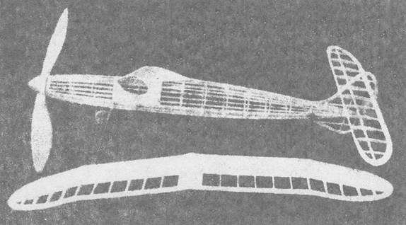
It’s long span and ample propeller
blade area insure long flights This model was
designed primarily for attaining high altitudes, and first
test flights were entirely up to expectations. However, after just a few
flights, the plane flew out sight and was lost. Although it set a new local
record of l8 minutes and was followed for 35 minutes.
the loss was heartbreaking because it prevented entering the model in
contests. The second test
model was improved and changed as experience with
the first one directed. Better performance was
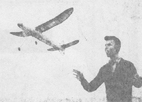
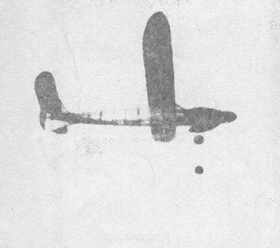
apparent immediately. Although the large prop turned slowly, the ship climbed
at a steep angle and attained altitudes as high as most gas jobs. The principle
behind this climb is simple! The ship was built extremely light and brought
up to weight rule with a heavy motor. Many model builders realize the
advantages of high power-weight ratio, but few use the extra power
efficiently. Therefore we took care to use as much stored energy as possible
towards getting altitude. A large prop and streamlined fuselage seemed to be
the logical combination. The fuselage was
especially designed to give a smooth airflow around the wing and stabilizer
as well as prevent burbles over the fuselage during the climb. The only time
the model had a chance to partially show contest ability was at a meet in
Tacoma, Washington, though a cold, gusty wind made long flights impossible. In spite of this high wind, the plane flew very
steadily and placed first with a three flight average 2 minutes. At this time
only three- quarter maximum winds was used. Later it was
found that the model averaged from 2:30 to 3 minutes with maximum turns in
calm air. We warn you, if there are any thermals around, the ship is sure to
soar away! If results with
the smaller ship are any indication, a scaled-up ship of Wakefield size
should out-perform anything in the field. If you want a super ship for 1941,
let's start construction. Fuselage At first this
type of construction may appear difficult, but with a little practice
streamlined fuselages can be made as light as the box type, and without spending
very much more time. First, a full-size drawing of the side view must be
made. For this purpose dimensions to the center line are given on Plate I. By
drawing 1/2" squares, the rudder is drawn accurately on the side view.
After this is done, the keel and rudder outlines, which are cut front medium
1/8" sheet, are glued together and pinned to the drawing. The rudder is
flat and can be completed on the drawing. Be sure that the 1/8" square
piece on which the stabilizer is mounted is parallel to the center line. While the
outline and rudder are drying, the formers should be cut. All except special
formers, are drawn full size on Plate II, giving the outside outline only.
These formers are 1/4" wide. The complete outline of the special formers
is given on Plate II. Note that the formers are cut from laminated balsa
sheet; this not only adds strength to the fuselage, but allows use of lighter
wood. Laminating is a simple process: Lay out a balsa sheet on a flat surface
and from another balsa sheet, cut short lengths equal to the width of the
first sheet. Glue these crossgrain After all
formers are cut glue half of them in place, following the outline the
drawing. When dry, lift this completed half from the drawing and glue the
remainder in place. The cabin top must be glued in place before formers can
be added, because they are glued to this top. When the formers are in place,
the 1/8" square side stringers should be glued in the notches. In order
that the fuselage be straight, stringers should be of equal weight and
strength and glued on at the same time. Before putting
on the 1/16" square stringers the landing gear and rear motor anchor
should be completed. The landing gear is secured with plenty of glue, gussets
and silk strips. The rear motor anchor is a short length of 3/16"
diameter aluminum tubing, which fits through the hole cut in the gussets
around former N. Be sure to cut the aluminum fitting shown on Plate II to
face the gussets: this adds strength and keeps tubing from pulling out. Tubing is used
for a motor anchor because a piece 1/8" wire may be slipped through it
and used for holding the model when winding. With this method no strain is
put on the fuselage when stretching the motor out to "pack
in" turns. Next the
1/16" square stringers and cabin covering are added. The position of the
stringers is marked on the formers. Note that notches are not cut for
1/16" stringers. The cabin covering is shown half size on Plate II and
will have to be scaled up. The direction of the grain is especially important
to facilitate brending. When the fuselage is finished it should be sanded
carefully in order to give a smooth covering. Wing and Stabilizer The wing has no
center spars; strength comes from the 1/32" sheet covering which also
prevents excessive sag between ribs. Full size airfoil sections are given on
Plate II. This airfoil was developed by modifying the Gottingen 176 which has
excellent characteristics at low speeds. Make a template and cut the required
number of ribs. Lay out a full size drawing of the wing and stabilizer and
construct them in the conventional manner. Taper the trailing edge before
gluing in place. After dihedral is put in cover the leading edge with sheet.
It is advisable to sand the sheet smooth on a flat surface before applying,
otherwise it will sand through at the ribs. At the center
section, the wing is covered both top and bottom with 1/32" sheet. Note
that this sheet must be glued between the ribs so it will be flush with the
airfoil outline. The center rib is cut flat on bottom so that a piece of
1/16" sheet, which fits the cabin top, may be glued flush with it. When
this piece is glued to the center rib there will be an open space between the
1/16" sheet and the 1/32" sheet on the bottom camber. Fill this in
with sheet balsa and fillet with balsa dust and dope. The wing is held in
place by rubber bands stretched from two hooks anchored to the keel near the
leading and trailing edges. Stabilizer
construction is so simple that no difficulties should be encountered. After
it is covered it is glued firmly to the rudder and braced with 1/32"
wire, shown on the front view. Note that the tab, which is soft 1/8"
sheet, is hinged with thin sheet aluminum. Propeller and Spinner Success with
any model depends largely on the propeller, therefore great attention should
be given to this. Carve the blank as show on Plate I. The approximate blade
shape can be determined by the dotted lines on the blank. The blades are about 1/8" thick half way to the tips After the prop
is finished bend the folding-prop lifting to fit the curve. These fittings
are lettered A, B and C on Plate II and correspond to the fittings shown on
the prop details on Plate I. When these parts are glued securely in place the
blade breaks should be cut. On folding props it is important to have the
blades free enough to fold, but tight enough to hold their pitch. Washers
should be soldered to the rubber-tensioner spring to keep it in place. The
bobbin also should be securely fastened to the prop shaft. When making the
hook which fits into former A, glue in the aluminum fittings (A) well so that
it will hold thrust adjustments. The spinner is
carved or turned from a block with the grain parallel to the thrust line.
Finish the outside first and then cut it in half and hollow out to about
1/8" thickness, Glue the halves together and cut the completed spinner
so that it fits tightly over the prop hub. When winding the spinner is
removed. Flying On the side
view the position of the center of grainy is shown: it must be in this
position or slightly to the rear in order to obtain the best glide. The
original ship was powered with 16 strands of 3/16" brown contest rubber.
With this motor the prop run was about 1:15 minutes. On the second model 20
strands of 3/16" brown contest rubber, 32 inches long, was used. The
motor run was slightly under the minute mark, but altitude attained was much
greater than with the first motor. When lubed and stretched five times its
length, 700 turns can be packed into the
motor. Test flights
should be made with a gradual increase in turns. The model climbs and glides
in right-hand circles. There should be a slight wash-in on the right wing and
the tab turned slightly to the right. Be sure to put in the correct amount of
right and down-thrust. If the model
stalls check center of gravity and thrust adjustments. If it dives or glides
steeply, increase the wing's angle of incidence and move the center of
gravity to the rear. Due to its stable characteristics, you should have no
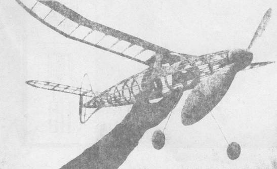
trouble adjusting the model if your surfaces are set as directed. Notes The high
mounted stabilizer seemed to increase the glide and spiral stability. Retractable
landing gear should increase performance, but is not advised unless you have
a good take-off and landing spot. If retractable gear is used be sure to fix
it so that you can leave it down for test flights: it will save the covering
on the bottom of the fuselage. The fuselage
was covered with strips of tissue, grain running lengthwise. The wing was
covered with the grain running spanwise. After the dope was applied, a coat
of glass was added to keep the tissues from tightening to the point where it
pulls in stringers and causes a sag between ribs. When yon wind
to maximum, be prepared to chase cross-country. Its fine flying
qualities and appearance will make you proud of your ship. Scanned from
June1941 Model Airplane
News
|