THE author used medium weight balsa
for all parts except the landing gear which is hardwood dowel. The model is
designed as closely as possible with available data to the scale of 1/2"
to the foot. The only part not to scale is of course the propeller, which
however is realistic and close to scale. Built very lightly, the author's model
weighs only 1/2 oz.
The fuselage is constructed first,
the two flat sides (shown in solid black) being laid out directly over the side
view. Study your plans carefully and note the solid 1/16" balsa side
section at front of fuselage; also note gussets at the junction point of wing,
and the small gusset at tail of fuselage to provide solid juncture point for
the elevators. All longerons, uprights and diagonals are of 1/16" sq.
balsa. Join the fuselage sides first at front and back, then add all remaining
crossbraces which are also of 1/16" sq. stock.
The fuselage of the real E-III was
square except for the three formers at front and on top of fuselage. These
formers, shown on Plate 1, are cut from 3/64" sheet stock and cemented in
place as indicated. The stringers are 1/16" by 1/32" and are cemented
in notches on formers. Now from a small block of balsa carve the two cowl
fairing pieces to outline; note the dotted lines on side view of fuselage.
Construct the motor cowl next,
cutting the two formers from 1/8" sleet stock. The front plate is clearly
shown on the front cowl former pattern by dotted lines; it is cut from
1/16" sheet stock with a small hole as indicated for the nose plug. This
front plate is cemented to the back of the front cowl former.
The cowl is formed by connecting the
two formers by 1/16" sq. Stringers placed in notches, the stringers being
only 7/16" long. This assembly is now covered with 1/64" sheet balsa.
When dry, cowl may be sanded to crossection indicated in side and top views,
and glued in place. With cowl in place and cement dried, streamline the two
side fairing pieces, using razor blade and sandpaper. (The author finds the
small fingernail emory boards used by his wife very handy for such streamlining
etc.; they can be purchased in most dime stores.) With the cockpit outline of
heavy bond paper and the tail skid in place, only the rear motor hook is
necessary to complete fuselage. This latter part is a small 1/16" diameter
hardwood dowel inserted through sides at point indicated just forward of
elevator by small black dot on side view.
The tail surfaces are next on our
production list. The rudder is simply cut from 1/32" sheet, and the
elevators are built of 1/16" flat stock of widths indicated on Plate 1.
Elevator should be built in one piece, so it is essential to complete left
half by tracing right half and reverse the tracing. Elevator is flat without
camber.
Wings are next. Note that two rib
outlines are shown on wing plan. The author used the scale rib on his model with
excellent results. However, the less experienced builder may prefer to use the
non-scale rib with camber on top surface only. The latter rib has the added
advantage of being deep enough to accommodate a 1/16" sq. spar. The
author's model with the scale rib has no spar and may be duplicated
successfully if the builder is cautious and accurate in his work. In any
event, the wings are constructed directly over the plans. The right wing plan
may be duplicated by tracing and reversing. Crossections of leading and
trailing edges are each 1/4" wide. The wing tips are of 1/16" flat stock.
Tips are easily cambered to same curve as top of the rib by soaking in hot
water and allowed to dry. The small circles on the third and fifth ribs are the
points at which the wires attach to wing. These points can be easily reinforced
by a cement coating, or the builder may wish to reinforce the sides of the ribs
with small balsa scraps.
With fuselage, tail surfaces and
wings finished, we are ready to cover; that is, after all frameworks have been
sanded smoothly with very fine sandpaper, or preferably with the fine side of
previously mentioned emory board.
Now comes the job which can ruin the
most carefully constructed model. Caution - take your time! To make the model
as light as possible, the author used (and recommends) lightweight colored
tissue. Since most German World War I fighters were gaily colored, a pleasing
effect was gained by using bright blue tissue for the fuselage, and yellow for
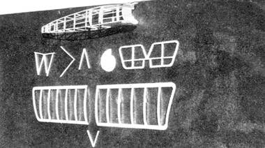
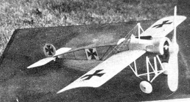
the wings and elevators. Now note accompanying photographs. From the solid
sheet sides back to the second upright, use one piece of blue tissue; between
second and third uprights use a small piece of white tissue (this gives a white
background to the insignia); and from third upright to rear, use another piece
of colored tissue.
The author at this point would remind
the builder that when covering all parts it is desirable to cover with the
tissue grain running the longest way. The curved portion of the fuselage bottom
just forward of landing gear is best covered with bond paper; aft of this, use
one piece of blue tissue. The small turtle deck just aft of cockpit is covered
with one piece, while the entire flat back portion of top is covered with
another single piece. Forward of cockpit, several small pieces can be used to
secure a smooth job. The front portion of fuselage is later color doped.
Now cover elevators, using one piece
of yellow tissue on each side. Trim first side covered with razor blade so that
no tissue extends beyond edges. A margin of 1/8" all around elevators
should remain after other side is covered. With care, all exposed wood portions
can be covered by utilizing this margin.
Rudder, being solid 1/32" sheet,
is not covered; it is instead given a light sanding, and a small bit of clear
dope is rubbed with index finger into each side. This gives a smooth light
background for applying insignia.
Wings are carefully covered, one
piece to each side. If scale ribs are used it will be necessary to put tissue
cement on bottom of each rib so the tissue will adhere to the concave surface -
otherwise spread tissue cement (or clear dope, which author prefers to use)
only on outline of surface being covered.
With covering completed, spray all
parts with an atomizer taking care that the wings do not warp. Clear dope is
used on fuselage only! Do not dope wings and elevators; to do so will cause the
light framework to warp.
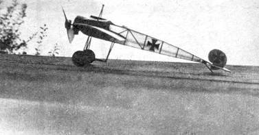
Now for the landing gear which is
made of 1/8" by 1/16" hardwood strips sanded to streamline shape.
Check accompanying photo of framework, then construct directly over plan on
Plate 2 the front vertical member of the landing gear. This front framework
consists of struts A, A, B, B, and C. When dry remove from board and construct
the rear vertical member which is merely a "V" of struts A, A. The bottom,
or horizontal assembly, is made in like manner directly over plan on Plate 2.
When these members are thoroughly dry cement them in place, using plenty of
cement and being careful to observe from side view, Plate 1, that the rear
"V" member slants forward very slightly. When attaching front and
rear struts it is best to remove tissue very carefully from framework at point
of attachment. Checking front view, install small music wire axles in proper
place; bind same with thread and cement firmly.
Now install the cabane strut
(inverted "V") just forward of cockpit in same manner as landing
gear. It is built over front view plan and is cemented in place at this time.
Note the small rectangular block at top of cabane strut; this is made of scrap
balsa and is cemented securely in place.
Wheels are made lightly in following
manner: on 1/8" sheet stock, using a compass, draw an outside circle
1-1/8" diameter, and inside circle 7/8" diameter. Cut out inside
circle first, then very carefully the outside. Wheel disks are made by cutting
from bond paper, four disks 1-1/16" diameter. Noting Plate 2, you will see
that the wheel disks are slit and overlapped 1/8". This makes a shallow
cone for each side, light yet sufficiently strong for this little plane. A
simple but effective bearing is made at center of, each disk by making a small
spot of cement. Wheels are held in place on axle by a drop of solder, or
another drop of cement.
Now for assembly. Cement elevator in
place with no incidence, then rudder. Wings are cemented in place without
dihedral and with 5° positive incidence.
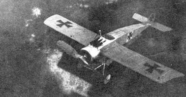
The front portion of fuselage,
noting, photos, the motor cowl, landing gear and tail skid can at this time be
color doped silver. Windshield is cut from celluloid according to front view;
machine guns are made from balsa scraps, doped black and cemented in place just
in front of cockpit.
A suggested dummy motor for the flying
scale builder is shown on Plate 2 at top of same, and for the detail addict a
complete dummy motor of nine cylinders may be placed inside the cowl of a nonflying
model. The dummy partial motor is cemented to the sides of the cowl. Dummy
motor and front cowl plate, of course, are doped black.
Refer to photos and add landing and
flying wires; a small additional stress wire is added (as shown on front view)
between wing leading edge and point 1/4" to rear of cowl front. Add
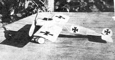
Maltese Cross insignia of black tissue.
Carve propeller from balsa block of
size noted on plans, add prop shaft of medium music wire, install same with
nose plug, washers, two loops of 1/8" flat rubber well lubricated and your
E-III is ready for test flight.
Test first by gliding into tall
grass. Small weights can be placed in back of dummy motor or under elevators
for balancing.
The author's E-III flew with no
balance weights, but materials etc. cause various models of the same plane to
have different characteristics.
The original plane used wing warping;
hence no aileron outlines are needed. Likewise, the entire elevator and rudder
assembly was hinged.
The enterprising builder can add
details from magazine photos. Take your time, work carefully, and you'll have a
very unusual model of which you can justly be proud.