|
Fundamentals
of Model Airplane Building A Complete Course for Beginners Who Wish to
Become Expert. How to Build an All Balsa Twin-Propeller Pusher Model Part No. 8 By EDWIN T. HAMILTON
AS OUR
eighth airplane model of this series, Mr. Grant has designed the first
twin-propeller pusher to appear in this course. As will be noted, we have
kept solely to all-balsa models to date and so the one shown here continues
that type of plane. This is done as part of a set program, to fully acquaint
the beginner with all types of flying models of solid construction before
taking him into the more difficult field of built-up construction. One of
the most outstanding features of this model is its exceptional soaring
ability which permits it to continue in flight long after normal propulsion
by motor has ceased. On test flights, it has remained in the air over two minutes
and flown a distance of two thousand feet. With
these unusual flying qualities, it nevertheless is of such simple
construction that the amateur can easily build it. The use of solid balsa
wings eliminates the tedious operations of built-up framework, which necessitates
a large number of ribs, intricate assembly and the covering of the structure
with tissue. It
represents the logical step toward contest models of like type and the beginner
should find it a stimulating and interesting building problem without the
usual expert workmanship being required. Flying the model will bring its
builder experience which will prove not only valuable but absolutely
necessary when tackling the launching, flying and handling of contest
planes. It
must be kept in mind that the whole worth of this course is to develop the
rank amateur into a well grounded, well informed expert. The entire course
has been laid out by your editor, Mr. Grant and the writer on this basis.
Don't shirk ... don't "skip," and you'll find that we have lived up
to the usual standards of UNIVERSAL MODEL AIRPLANE NEWS in giving its
readers only the best. A-Frame In a
twin-propeller model of this type, the fuselage is known as the
"A-Frame." This is because it is built to the general lines of a
capital "A." Such models are often referred to as "twin-stick
pushers." They are essentially outdoor models and have set up some of
the finest flight records known in the model airplane field. Two
balsa sticks, measuring 1/4" square and 36" long, form the
framework of the fuselage. These are joined together at the front end and
spread apart at the rear or trailing end, by wire. Cut two sticks to this
size, sandpaper each carefully and test to see that both are exact
duplicates. A
miter joint is cut at one end of the sticks, so that when they fit together,
the trailing or opposite ends will be exactly 10" apart when measured
from outside to outside of the sticks. This can be seen in the plans under
"Top View." Lay both sticks in proper position and then cement
their front ends together. Before applying the cement, squeeze the front
beveled ends together and then measure the distance the rear ends are apart.
If they are 10" from outside to outside,- or 9-1/2" from inside to
inside, the beveled ends may be cemented together. Hold them in place with a
model pin or a rubber band until the cement dries. Four
piano wire braces are used to hold the frame in proper form. The two cross
braces and the combination cans and center brace are all bent from 1/32"
diameter wire, which is approximately a No. 13 piano wire. The trailing end
brace because of added stress, should be bent from 3/64" wire. This is
about a No. 21 gauge. If you cannot purchase wire of this diameter, do not
use any of less diameter than a No. 16, which is .037". Bend
the two cross braces, as shown in the plan under "Cross Braces."
This plan is given full-size except for its length which had to be cut down.
It is 7-1/2" long from bend to bend, as shown. The
third bracing wire which is bent to form a "can" on each end is
shown under "Cans" in the plans. This is full-size. Cans are used
to keep the rubber in place against the sticks and Mr. Grant has designed
this combination brace and can to cut down operations and weight. The
last brace is located at the trailing ends of the sticks. It is bent from a
10-1/4" long piece of 3/64" diameter wire. Both of its ends are
bent for a distance of 3/8" which leaves 9-1/2" of its length
straight. This is shown in the magnifying-glass view in the plans under ''Top
View." When
all these wires have been bent to shape, they are assembled on the A-frame.
The trailing brace should be attached first. As a thread binding is used
around its bent ends and the propeller bearings of the model, the latter
should be attached at the same time. Obtain
two propeller bearings of good size. These are cemented to the outer sides of
the sticks, while the bent ends of the brace are cemented to the inner sides.
When all are in place, bind the bearings and the ends together with thread
and apply a thin coat of the cement over the thread for added strength. Note
this assembly in the magnified view of the plan under "Top View." The
two cross braces are now cemented in place. Note that their bent trailing
ends are lashed to the inner side of the sticks 14-1/2" from the
trailing end of the A-frame. Cement and lash the four bent ends of these two
braces in place. The brace having the cans on its ends, is located 18"
from the trailing end of the assembly and crosses the two cross braces at the
point where they cross each other. Mark a point 18" from the trailing
end on each stick, pass the bent notch on each end of the brace over the
sticks, cement and then bind with thread. Cement is applied over all thread
bindings for added strength. Complete the brace assembly by binding all three
of these center braces together at the point where they pass each other in
the center of the frame. A nose
hook, which is shown in the plans full-size under "Nose Hook," is
bent from No. 13 piano wire. This holds the "S" hooks of the motor
and at the same time strengthens the nose joint formed by the two sticks.
After bending to proper shape, slip it over the joint of the two sticks and
cement firmly in place. It is then bound with thread, which is given a thin
coat of cement over its top to add strength. Up to
this point we have not spoken of the top or bottom of the stick. As the
curved bends in the cans are to hold the rubber strands of the motor, the
opened side of these cans must be the upper side of the frame. The frame is
completed by cementing two small blocks on the side of each stick. These
blocks are shown in the plans under "Top View" in the upper
left-hand corner. Cut two blocks measuring 1/8" thick, 1/4" wide
and 2-1/2 long. Cut two additional blocks 1/16" thick, 1/4" wide
and 1" long. The long blocks are cemented on top of the sticks 4"
from their leading, or "nose" end. The smaller blocks are then
cemented on top of these long ones with the leading ends of both flush with
each other. This completes the A-frame. Elevator The
elevator consists of a single sheet of 1/16" balsa with four ribs of the
same thickness. Square up a sheet of the balsa to measure 1/16" thick,
3-1/2" wide and 14" long. From each end, measure in 3-1/2" and
lay out the curves of the tips. Cut these to proper shape. Finish smooth with
sandpaper. The
elevator is now cut through its center into two halves of equal length. Cut
four ribs from 1/16" sheet balsa, as shown full-size in the plans under
"Elevator Rib." Note their location in the plan under "Elevator."
Apply cement to the ribs, bend the elevator carefully to fit their curves and
attach them in place. Hold with model pins until the cement has hardened. The
two completed halves are now cemented together with a 1-3/4" dihedral at
each tip. When perfectly dry, complete the elevator by carefully sandpapering
its entire surface. As rubber bands are used to hold it in place on the
A-frame, no metal fittings are required. Wing The
wing is of the same construction as the elevator. It differs very little from
other all-balsa wings given for other models in this course. It is made of
two pieces of 1/16" sheet balsa. Square up two pieces to measure
1/16" thick, 4-1/2" wide and 16-1/2" long. Measure 4-3/4"
from one end of each piece and lay out the curve of the wing tip, as shown in
the plans. Cut these to shape. Cut to
proper form eight wing ribs from 1/16" sheet balsa. The rib is shown in
the plan full-size under "Wing Rib." Note the location of these
ribs in the plan under "Wing." Apply cement to the ribs' curves,
carefully bend the sheeting around each, and hold with model pins until dry
and hard. The
two halves are now cemented together to give a 1-3/4" dihedral at each
wing tip. When hard, reinforce the joint by cementing leading and trailing
edge pieces to the underside of the wing. These measure 1/32" thick,
3/8" wide and 7/8" long, or the distance between the two center
ribs, Bend them slightly at their centers and cement them in place between
the ribs on the underside of the wing at its leading and trailing edges. Finish
the wing by carefully sandpapering its entire surface to a satin finish. As
the wing also, is held by rubber bands to the A-frame, no metal fittings are
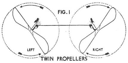
required in its construction. Propellers
In the
November issue, our first pusher model called for a left-hand propeller, the
use, carving and difference of which was fully explained, When two propellers
are used on a model, they must be so made as to turn in opposite directions, so
that the directional pull of the one will offset that of the other. For this
reason, twin propeller units are always made up of one right and one left
propeller. On twin - propeller pushers such as the one we are building, the
propellers are so mounted that each will turn up and out, as shown in Fig. 1.
In this view the eye rests on the concave side of the propeller's blades. All
the models having propellers in this course have had right-hand propellers
with the exception of last month's model, which was a left-hand propeller. It
will not be necessary, therefore, to repeat carving instructions for the
propellers required for this model. From blocks measuring 1" thick,
1-3/4" wide and 10" long, carve one right-hand and one left-hand
propeller. Equip them with propeller shafts bent from 1/32" piano wire,
(No. 13). These shafts are shown in the plan full-size under "Propeller
Shaft." Complete the assembly by adding two shaft washers to the
propeller shafts and then place them in position on their bearings. Motor Twin
motors for the twin propellers are used on such models as this. Each of these
consist of eight strands of 1/8" x 1/30" rubber. As considerable
"play" should be allowed for added power, the original length of
each motor should be at least 288" long or 24 feet. Tie the ends of each
piece together to form a single loop. From
No. 13 piano wire, bend two "S" hooks to shape, as shown in the
full-size pattern, in the plans under "S" Hook. Hook one end of
each over the nose hook and then pass four loops of the rubber motor over the
other ends. Weave the rubber strands through the cans and loop their other
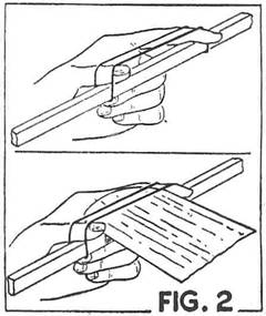
ends over the propeller shaft hooks, which completes the motor assembly. Assembly
With
the assembly of the motors completed, we have only to add the wing and
elevator to our A-frame to complete the job. Both these units are held with
rubber bands. Two bands are used for each. Note how this is done in Fig, 2.
Locate the trailing edge of the wing 6" from the trailing ends of the
sticks and fasten in place on top of the frame with the bands, The
elevator has its leading edge resting on the lower of the two frame blocks,
4-1/2" back from the nose. Attach in this position with two bands as
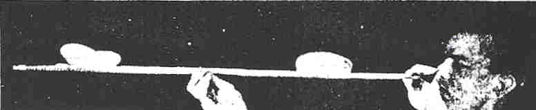
shown. When
flying the model, launch it in the manner shown in the photograph. It will be
found best to hold the propellers with one hand and steady the model with the
other rather than using the old method of "pushing" the model from
you with both hands on the propellers. If
more elevation is required the elevator may be thrust forward until its
leading edge is on top of the second and higher elevation blocks. Scanned From December 1934 Universal Model Airplane News
|