|
Fundamentals of Model Airplane Building A Complete Course for Beginners Who Wish to Become Expert. How to Build Your First Single Propeller Pusher. Part 7
By EDWIN T. HAMILTON
IN THE seventh model to be presented in this series, Mr. Grant brings to the reader the first single propeller pusher. It has proved to be a remarkable performer for an all-balsa plane. The difference between a "pusher" and "tractor" plane lies in the position of the propeller. If the propeller is in front of the main supporting surface, it is called a tractor because the propeller tends to pull the plane, If the propeller should be located behind the main supporting surface, the plane is called a pusher because the propeller tends to "push" the plane. As the propeller of this model is behind the wing or "main supporting surface," it is a pusher. It is likewise known as a "single propeller pusher" because it has only one propeller which is located behind the wing. Next month, we will give a "twin propeller pusher," which is so-called because it has two or "twin" propellers, both located behind the main wing. These models are often spoken of as "single-stick pushers" or "twin stick pushers," The chief problem of a single propeller pusher has been one of stability. This is because the twist of the motor stick and the torque of the propeller both act to make the model turn to one side. This fault has been overcome by raising the elevator well above the motor stick and giving it considerable dihedral. It will be found to fly in a stable circular path. Its climbing ability has proved remarkable. Under ordinary conditions, flights of two minutes or more can be easily obtained over a distance of from 1000 to 1500 feet, With six strands of 1/8" rubber, the motor may be wound 475 to 500 turns by hand. If lubricated and wound by a winder, this can be increased to 900 or 1000 turns. With a winding of 900 turns by the latter method, the model has a pitch distance of 1500 feet. Pitch distance equals the number of turns stored in the motor multiplied by the pitch of the propeller, which in this case is 16". This estimate of distance will prove a conservative one. The model is simple to build; will glide well at a steady, flat angle, and will turn in performances equal to the best of contest models. Under ordinary conditions, it will reach an altitude of 200 feet and make a splendid appearance in the air, Here's your chance to build and fly an all-balsa, single-propeller pusher second to none! Let's get busy, build this clever plane and know the thrill of flying the best. The building instructions for this model will not be as detailed as most of the preceding, ones because its lines so closely follow those of the endurance model given last month. It might be well to turn to your October issue (Page 9), and again read the instructions given there. You will find both building operations considerably the same for that plane and the one given here. However, there are several points quite different, which will be fully explained here.
Motor Stick
The motor stick is a single piece of balsa measuring 1/4" thick, 3/8" wide or deep, and 26" long. The top of the stick is left perfectly flat, as shown in the plans under "Side View," while the bottom has both ends tapered. At the front, this taper is started 3-3/4" back, it tapers from the original depth of the slick to 3/16" at the front. (Note that the "front" of the motor stick of this model is exactly opposite from the front of all the other models given so far, as this is a pusher plane and therefore has its propeller at the trailing or back end of the stick). At the rear end of the stick, the taper starts back 3" and is beveled from the original depth of 3/8" to 3/16" at the end. At this same end on its upper side, the usual propeller bearing is cemented and silk bound to the stick, as shown in the plans, A nose hook is bent from No. 13 piano wire to the form shown in the plans tinder "Nose Hook." This is shown full size. It is then cemented around the front end of the stick, as shown in the "Side View." On the underside of the motor stick, 3-3/4" back from its front end, a small 1/16" x 1/4" x 2" long block is cemented in place. This offers less elevation for the leading edge of the elevator should this prove necessary, The front clips of the elevator fitted over this block, which in turn pulls the leading edge lower.
Elevator
Make the elevator in two duplicate halves. Cut these to shape from two 1/32" thick, 2-7/8" wide and 6-1/4" sheet balsa, as shown in the plans under "Elevator." The grain of the wood should run parallel to the center line of each half wing. Turn to the ribs in the plan, which are shown full size. These are of 1/16" balsa. Four are required for the elevator; two No. 4 and two No. 3. Cement the ribs in place, as shown in the plans and hold the sheet balsa to them with model pins until dry. Join the halves together with a 2" dihedral. Flatten the underside of the leading and trailing edges between ribs No, 3, as shown in the edge view. Two pieces of No. 6 piano wire from each of the two necessary elevator clips. Note these in the plans under "Elevator Clips." These are bent and attached exactly the same as the wing clips of last month's model. Cement them in place on the elevator, which completes this part.
Wing
The wing, like the elevator, is made in two duplicate halves. Its basic construction is the same as the elevator. Each half is cut from sheet balsa measuring 1/32" thick, 4" wide and 13-1/4" long, Note that both the leading and trailing edges are tapered in toward the center of the wing at its tips an equal distance. Each half requires four ribs, which are shown in the plans under "Ribs" as Nos. 1, 2, 3 and 4. Cut the halves to shape, cement the ribs in their proper positions and hold with model pins until dry. The two halves are then cemented together at a 2-1/4" dihedral for each wing tip. A small fin is attached to the center-top of the wing to lend stability. This is shown in the plans under "Fin." Note that it is cut to shape from 1/16" sheet balsa and that its bottom edge must be shaped to fit the curvature of the wing made by the rib No. 1. When completed, cement this fin over the joint formed by the two halves. Wing clips are bent from No, 6 piano wire, as shown in the plans under "Wing Clip." These are the same construction as those of the elevator and are held in place on the stick as described in the October issue. (See October issue, Pages 9 and 11, Figs. 3 and 1). Propeller
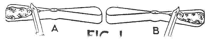
Mr. Grant has elected to use a left hand propeller on this pusher model. Usually when only one propeller is used on a model, it is a right hand propeller. This means that the propeller turns clockwise when viewed from the rear or concave side of the blades. In other words, it is wound in a counter-clockwise direction and when released, it travels in the same direction the hands of a clock turn. When a propeller turns counter-clockwise, when viewed from the rear or concave side of its blades, it is known as a. left hand propeller. In other words, it is wound in the same direction as that in which the hands of a clock turn, but when released, it travels in the opposite direction to those of a clock. This explains the left and right hand propeller, but has nothing to do with a pusher or tractor propeller. As far as the actual propeller is concerned, there is no difference whatever between a pusher and tractor. Both are carved in exactly the same way. Both are mounted with the concave side of the blades trailing. In other words, when viewing the propeller from behind the model, you will always see the concave sides of the blades, The only difference between a tractor and pusher propeller is that the hook of the propeller shaft extends out from the hub of the propeller on different sides. The shaft of a tractor propeller extends out from the hub on the concave side of the blades. The shaft of a pusher propeller extends out from the hub on the opposite or convex side of the blades. A tractor propeller can be changed into a pusher propeller by simply changing the propeller shaft so that the hook of the shaft is on the other side. The carving of a left hand propeller is not a necessity for this model. A right hand propeller will serve quite as well if the shaft is inserted from the opposite side. However, a left hand propeller should be carved for this model, in order to be able to wind it by hand clockwise the same as right hand tractor propeller is wound clock wise. The carving of such a propeller is exactly opposite to that of a right hand propeller. This is shown in the illustration Fig. I, which shows the start of carving one. The first cuts are made along the left top edge of the blank, as shown at "A," while a right hand propeller would be started at the right top edge, as shown at "B." All actual carving steps are the same, after the blades have once been started as at "A." Bend a propeller shaft from No. 13 piano wire and insert it as you would a right hand propeller so that the hook is on the concave side, and the job is finished.
Assembly
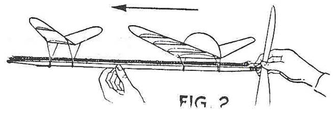
Study the plan under "Side View." Bend an "S" hook from No. 13 piano wire. Six strands of 1/8" flat rubber are used for the motor. Obtain a piece about twelve feet long, tie its ends together and loop it into six strands between the "S" hook at the end having the nose hook and the hook of the propeller shaft. The clips of the elevator and wing are then placed around the stick and held with rubber bands, as explained in the last article in the October issue. Place both these surfaces exactly as shown in the plans. Hand wind the motor for trial flights and launch it as shown in the illustration Fig. 2
Scanned from November 1934 Universal Model Airplane News
|