Fundamentals of Model Airplane Building A Complete Course for Beginners By EDWIN T. HAMILTON HERE is the sixth model of this
series. Mr. Grant has designed, built and tested it with two major considerations
in mind, The first of these is to bring the reader additional building steps,
as has been done with the preceding five. In this progressive manner, the
reader will gradually master all construction details and operations in the
building of model airplanes. The second consideration is to give
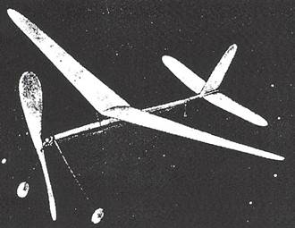
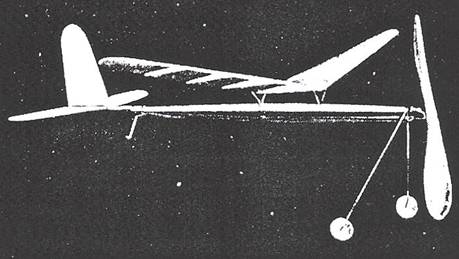
the reader as fine a model as possible. In this all-balsa, R.O.G.
(rise-off-ground) tractor, Mr. Grant has produced one guaranteed to out-fly
any others so far designed in this particular class. How well he has
accomplished his task will become evident to all who build and fly the model
presented here. On actual flight tests, its
behavior was remarkable. With its motor only two-thirds wound by hand, it
rose to an altitude of some two hundred feet and covered a distance of eight
hundred feet. Without the aid of air currents, but wound with a winder, it is
capable of a flight distance of over twelve hundred feet and a total duration
of from ninety to one hundred seconds! Given a slight up-draft, it will
fly in. definitely to give a performance similar to the finest of outdoor
contest models. Its large stabilizer; long stabilizer moment arm, and the
combination of dihedral, sweep-back and low center of gravity, gives to this
model a stability second to none. Rising from the ground in a beautiful
sweep, it will quickly adjust itself to existing air conditions, although it
is not advisable to fly it in extremely rough and windy weather, as it weighs
only 1-1/8 oz. So let's get busy and build this
latest creation of a designer who is not afraid to guarantee his product to
beginners and experts alike. Motor Stick The motor stick is shaped from a stick
of medium hard or hard balsa wood. It should measure 3/16" thick, 3/8"
wide and 18" long after being cut and sandpapered smooth. As will be
seen in the plans under "Top View," it retains its original thickness
along its entire length, but its width varies from 3/8" to 3/16". This is shown in the plans under "Side View," Note that this variation in width
is obtained by shaping the upper edge of the stick only, while the bottom
edge remains perfectly straight. It is in the form of a taper and is now
ready for laying out. Choose either end as the front or leading end of the stick and so
mark. From this end, measure a distance of 7" along the stick. From this
point, the stick is tapered from its original width of 3/8" to a width
of only 3/16" at the front end. Cut this taper and sandpaper smooth, A distance of 8" is now
measured from the rear or trailing end of the stick. From this point the
stick tapers from its original width of 3/8" to a width of 3/16" at
the trailing end, The remaining 3" between these front and rear tapers
remains 3/8" wide. Cut this second taper and sand smooth. The upper front edge of the stick
is now rounded, as shown in the plans under "Side View." Tail Boom The tail boom is of the same
grade of balsa wood and when sandpapered smooth, should measure 1/8"
thick, 3/16" wide and 6" long. Choose either end as the front and
so mark. From the front end, the boom retains its original 1/8"
thickness for a distance of 2-5/8". Lay this out and mark. From this
point to the rear end of the boom, the thickness is tapered from 1/8" to
1/16". Note that this taper is cut on one edge only, which becomes the
bottom edge, while the other edge which becomes the top edge of the boom,
remains perfectly straight. Cut this taper and sandpaper smooth. The upper
front edge of the boom is now rounded, as shown in the plans. Two small balsa blocks measuring 1/8"
x 1/8" x 3/4" long are now cut and cemented on both sides of the
boom 2-1/4" from its front end, as shown in the plans under "Top
View." These are to add strength to the boom at its weakest point, as
well as to steady the elevator. Shape their bottom edges to match the taper
of the boom. The boom is attached to the stick
at its rear end with cement reinforced with thread binding. Note that its
3/16" width continues the 3/16" thickness of the motor stick. Care
must be taken to cut away the top edge of the motor stick, so that when the
boom is attached in place, its straight top edge will be parallel with the straight
bottom edge of the motor stick. At the same time, the sides of the boom must
be in a straight continued line with those of the stick. The front end of the
boom overlaps the rear end of the stick l" as shown in the plans under
"Top View." Cut the top of the stick as
required. Before the boom is attached, however, the combination rear hook and
tail skid must be bent, as these three parts - the stick, boom and this metal
fitting are all cemented and bound together. The combination rear hook and
tail skid is bent from No. 13 piano wire. As it is shown in the plans full
size, it should be bent to match the one given at the top of the plan
perfectly. Cut a small groove along the top-center of the boom slot in the
motor stick, so that the top bend of the skid will fit into it perfectly.
When in place, coat the slot with cement and place the boom in position on
the stick. Now coat both the stick and the boom with cement and then wrap
with thread until all three parts are held tightly. When completed, the
thread may be given an outside coat of cement to further strengthen it. Elevator The elevator is cut from a piece
of 1/32" sheet balsa measuring 3" wide and 11" long. Note the
elevator shown in graph at the bottom of the plan. Rule paper with 1/4"
squares, copy the elevator, fullsize on this paper, trace it on the balsa
sheet and cut out. Slightly round and smooth all edges and then carefully
sandpaper the piece until slightly thinner than its original thickness. Rudder The rudder is cut from a piece of 1/32" sheet balsa
measuring 3" wide and 4-1/4" long. It is shown in graph at the
bottom of the plan, Proceed to cut this piece in the same manner as was the
elevator. Finish with sandpaper in the same manner. As the rudder is
cemented to the elevator, it may be assembled at this time. Two sheet balsa strips are added
to the sides of the rudder to increase the thickness of its edge for
cementing purposes. These are shown in the plans under "Side View."
Each should be cut to measure 1/32" x 3/16" x 3" long.
Sandpaper them smooth and then cement them on each side of the rudder along
its straight bottom edge. This assembly is then cemented to
the center of the elevator, as shown in the plans. The trailing edge of the
rudder must be flush with that of the elevator, the rudder must bisect the
elevator, and the trailing edge of the elevator must form right angles with
the rudder. Wing
Study the plan of the wing. Note
that it is cut from two, pieces of 1/32" sheet balsa measuring 4' wide
and 13-5/16" long. Cut these two pieces to exact size. Note that one of
them is shown on the left side of the wing in the plans by dotted lines.
Measure 2" in from one edge and then draw a line along the center of the
wing board bisecting it. All measurements are laid out on each side of this
line. At the tip of the piece, measure 1" on each side of the line, Lay
out the trailing edge of the wing by drawing a line from the trailing end of
the inner end of the board to this 1" point. Draw a second line across the
width of the board at right angles to the trailing edge line so that its
forward end meets the inner front corner of the board. This line forms the
inner edge of one wing half. From the leading end of this
inner edge, measure 1/2" along the leading edge of the board. Now draw a
line from this point to the 1" point at the wing tip. This forms the
leading edge of the wing, Make a graph of the wing tip, trace it on the board
and cut out the wing half. The second wing half is cut out in the same manner.
Finish smooth with sandpaper. Both halves should now be tested
to see that when placed together they form a perfectly straight trailing
edge. If not, their inner edges must he sanded until a perfect fit is
obtained. At the same time, the entire wing span must measure exactly
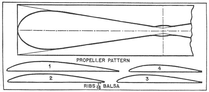
26". Each wing half requires four wing
ribs, which are shown full-size in the accompanying drawing. Trace these on
thin paper, transfer two of each rib on 1/16" sheet balsa and cut out.
Finish carefully with sandpaper. Assemble the ribs on each wing
half before joining the halves together. Note their positions as shown in
the plan under "Wing." Rib No. 1 which is the largest, is placed 1/2"
in from the inner edge and parallel to it. Rib No. 2, the second largest, is
placed 3-1/4" in from the inner edge or 2-3/4" in from rib No, 1.
The third rib is placed 2-7/8" from rib No. 2, while the smallest and
last rib, (No. 4), is cemented 3-7/8" from the wing tip or 3" from
rib No. 3. Apply cement to both the ribs and
the underside of the wing half and carefully bend the wing around the ribs.
Hold with pins until dry. The second half is assembled in the same manner. Balsa sheeting, measuring
1/32" thick and 5/16" wide, is cemented between ribs No. 1 and No.
2 on the leading and trailing undersides of each wing half for added
strength. The inner edges of each wing are now beveled to match each other
perfectly when the wing is given a 2-1/8" dihedral at each tip. Obtain this dihedral in the usual
manner and then cement the halves together. Two additional balsa sheetings
are now added along the underside of the wing at the leading and trailing
edges between the No. 1 ribs of each half. Like the others, these must
measure 1/32" thick and 5/16" wide. They must be cut 1" long,
bent to fit the dihedral angle and cemented.
Mr. Grant has developed a new
type of wing clip for this model. It consists of four pieces of wire, two of
them forming the leading edge clip and two the trailing edge clip. Note their
full-size form at the top of the plan. They are bent from No. 6 piano wire.
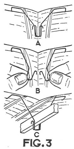
Bend two front clips and two rear clips. Instead of going directly into the
wing structure, these clips have a bent lip on them which extends inward on
the underside of the wing before they are bent up to enter its wood surface.
These bends are shown at "A" and "B". The former is for
the leading clips, while "B" is for the trailing ones. These clips come up to the edge
of the wing, extend along the edge, turn in at right angles, extend toward
the center of the wing and are then bent up and inserted into it. Note this
in the illustration showing the clip on the wing, marked Fig. 3. Test your
bends to see that the trailing clips are exactly 1/8" shorter than the
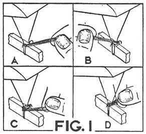
leading clips. The wing is attached to the motor
stick by spreading the hooks of each clip apart, passing them over the stick
and bringing them together under it, where they are held together with short 1/2-inch
long rubber bands. The attaching of these bands is shown in Fig. 1. Propeller
The propeller is carved from a
medium hard balsa block measuring 7/8" thick, 1-3/4" wide and
10" long. Lay out the pattern as shown full size in the drawing, and
then carve in the usual manner. Its hub is cut away on the inner side or on
the side from which the propeller shaft protrudes. Bend a propeller shaft from No.
13 piano wire to the exact size shown in the plans. Insert it through the hub
from the inner side, bend it around as shown, pull it back so that the end
enters the hub wood and acid cement for strength. Landing Gear The landing gear is bent from a
single piece of No. 13 piano wire, as shown in the plans, Note that this
piece extends up to the stick, goes forward along its bottom edges and then
forms a bend around the motor stick. In this way, it must be placed over the
motor stick from the stick's upper side, as shown in the small drawing of it.
However, before it is attached to the stick, wheels must be cut and the
propeller bearing must be bent. The wheels may be of hard wood
and if this is used, they may be 1-1/4" in diameter and 3/16"
thick. If balsa wood is used, they should be 1-1/2" in diameter and 1/4"
thick. Cut these out, sand to perfect circles and attach to the landing gear. A regulation propeller bearing is
cemented to the underside of the motor stick. Slip the landing gear over the
stick, apply cement and then bind both the gear and the hearing with thread.
Apply a coat of cement over the finished binding for added strength. Note
that the landing gear wire at the lower end extends back a distance of 1-3/47". Motor Power The motor consists of six strands
of black or brown rubber and is attached to the combination rear hook and
tail skid by a second hook, known as an "S" hook because of its
shape. Note this at the top of the plan. It is also bent from No. 13 piano
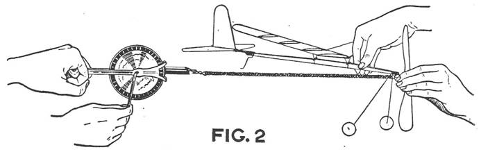
wire. Such a hook permits the motor to be wound with a hand winder, such as
is shown in Fig. 2. Tie the length of rubber together
into one loop and then pass it between the "S" hook at one end and
the propeller shaft at the other. For proper sag in the motor, a length of
100" should be used. If you wish more power, another strand may be added making
seven in all. In this case, one end is tied to the propeller shaft hook,
wound hack and forth between this hook and the "S" hook, and then
the free end tied to the "S" hook. Flying
For all strong motors a winder
should be used. These may be purchased at any model airplane supply store and
are used as shown in Fig. 2. While one holds the propeller shaft away from
the bearing, the other attaches the hook of the winder over the "S"
hook, stretches the rubber motor about four or five times the length of one
strand and begins to wind, While the winding proceeds, the one doing the
winding should slowly walk toward the model. With such a winder, this motor
can be given about 550 to 600 turns when a lubricant is used. Such
lubricants can be purchased, applied before winding and then carefully
washed off before the model is stored away between flights. If the winder is not used, a
hand-winding can he given the motor of about 300 turns. Through the balance
method, locate the center of gravity, as shown on the plan by "C.
G." in the side view. The location of the wing is determined from this
point of gravity. Note that the leading edge of the wing is set exactly 1-3/4"
in front of this point. Set the wing at this position,
wind the motor and launch the plane on its maiden voyage! Scanned
From October, 1934 Universal
Model Airplane News
|