Fundamentals of Model Airplane Building A Complete Course for Beginners Who
Wish to Become Expert. How to Build a Fine Flying Practice
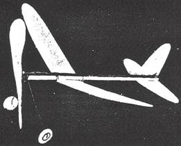
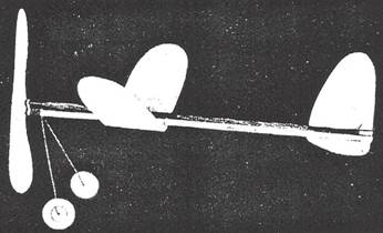
Model-Part No. 5 By EDWIN T. HAMILTON WE PRESENT here our fifth article on model airplane construction.
This little model typifies the principles of design which your editor,
Charles H. Grant, has been advocating in his popular series of articles
"The Aerodynamic Design of the Model Plane." Freak tests with this
model have proved beyond doubt the soundness of Mr. Grant's designing
principles. Possibly the most interesting test made with this model,
and by far the most important one to the average model airplane builder, was
the poor launching test. The model was released with its wings at a
ninety-degree angle to the horizontal. While this would spell ruin to the
flight of the majority of models, it immediately righted itself and flew
perfectly upon being launched. Many other severe tests were given it, both in the method
of launching and the weather in which it was flown, but in all cases perfect
flights resulted. Its performance and stability are exceptional. Out of some
ten flights it averaged, when hand wound, 30 seconds duration covering an
average distance of 450 feet. For the beginner who has not yet developed the
technique of model plane flying, it will prove especially adaptable. Here is a model guaranteed to be a "sure fire"
flyer under all conditions. It will prove a splendid practice model for
every beginner, whether he is building his first model, or for the expert
wishing to test the aerodynamic designing principles upon which it has been
created. Motor Stick The motor stick of this model consists of a single stick of
balsa wood. When sandpapered smooth, it must measure 3/16" thick,
3/16" wide and 14" long, as shown in the plans under "Top
View." Do this sanding with the aid of a block, as shown in the May issue
under Fig. 5 on Page 9. Elevator The elevator requires a piece of sheet balsa measuring
1/32" thick, 2-3/4" wide and 7-1/4" long. A graph plan of its
form is shown at the bottom of the plan under "Elevator." Make a
copy of this on paper ruled with 1/4" squares. (See the June issue, Page
8 for instructions in this work). The elevator is then cut to its proper form. Make all cuts
just outside the lines so that its edges may be sandpapered smooth down to
the lines. When completed, it should be 1/32" thick, 2-1/2" wide
and 7" long, as shown in the top view of the plans under
"Elevator." Rudder As shown in the graph plan, the rudder is the exact size
and shape of one-half of the elevator. Divide the pattern of the elevator in
half, as shown by the dotted line in the graph, trace it on 1/32" sheet
balsa and cut out. Sandpaper its edges smooth and down to exact size. Test
for exact form by placing it on one-half of the elevator and seeing that it
is a perfect duplicate of the elevator half. Wing
Obtain a piece of sheet balsa measuring at least 1/32"
thick, 2-5/8" wide and 17-3/4" long. Study the top view of the wing
in the plans under "Wing." This shows the wing as it looks after
being bent around its two ribs, as shown under "Wing Section." The
width of the wing after bending is 2-1/2", but the original width must
be 1/16" wider to allow for its bend. In this manner, the wing must be
cut and its edge sandpapered down to 2-9/16" wide. The tips of the wing should he cut from a pattern made from
the graph plan under "Wing Tip." Cut and sandpaper the wing to
exact width, trace and cut one tip and finish this by sandpapering down to
the pattern line. The length of the wing is then measured exactly
17-1/2", the second tip braced, cut out and sanded smooth. Locate the exact center of the wing, draw a line from
side-to-side at right angles to the sides, and then crease along this line on
the upper surface of the wing. This permits it to be bent for the required
dihedral without severing the halves. Cut a dihedral block 1/8" thick, 5/8" wide and
2-1/2" long. This is shown in the plans under "Wing,"
"Top View" and "Side View." Shape the block in the form
of a triangle, as shown in the front, or edge view of the wing, so that it
can be fitted and cemented directly over the center creased line of the wing. The wing is now given its required 2-5/8" dihedral at
each wing tip. Place one side of the wing flat on the table and carefully
raise its other half until the tip is 5-1/4" above the table surface.
When in this position, test to see that the dihedral block fits the angle of
the two halves formed at their center. Hold in position, coat with cement
and press the dihedral block into the center groove formed by the two wing
halves. Small model pins may be driven through the underside of the wing into
the block until the cement has dried. They are then removed. After the cement has thoroughly hardened, the wing ribs
are cut and cemented into place. These are carved from 1/8" thick,
5/16" wide or high, and 2-1/2" long balsa wood pieces. Note their
exact form in the graph plan under "Wing Section." Two of these
will be needed. Carve until exactly like the full-size pattern and finish
smooth with sandpaper. They are now cemented in place on the underside of
the wing. Locate their position from the plan under "Wing." Each of these two ribs are attached 3-3/4" from the
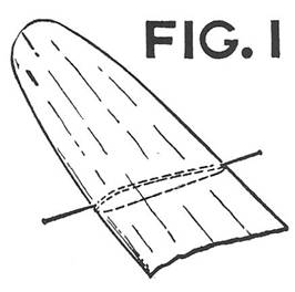
center line of the wing. Coat the top of one with cement, press it into place
at the leading edge and force a model pin into it through the wing at the
angle shown in Fig. 1. The wing is then carefully bent around the top curve
of the rib and its trailing half held with a pin as shown. The second half of
the wing is bent and the rib attached in the same manner. Note that these
ribs extend slightly below the leading and trailing edges of the bent wing.
Complete the wing by cutting a small elevation block. This is shown at the
trailing edge of the wing in the plans under "Side View." It must
be cut 3/32" thick 1/4" wide and 5/8" long. Cut this to size
and sand all sides smooth. This elevation block is now cemented on top of
the dihedral block at the trailing edge of the wing, as shown in the plans
under "Side View." Propeller
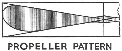
The propeller is carved from a blank cut from a 11/16"
thick, 1-3/8" wide and 8" long balsa propeller block, The propeller
given last month was carved direct from the block but this one has its blank
cut out first and the carving done from this blank.
The form shown for this model is known as a "U. S.
Navy" type propeller. It is the most popular type of propeller for such
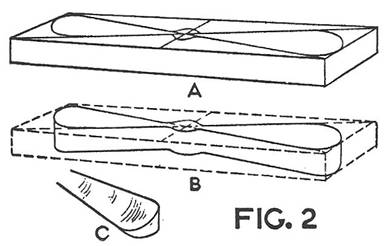
models. Study the full-size pattern of the propeller. Draw two diagonal lines
across your block
and then draw within these lines the form of the blades, as shown, The block
is now ready to be cut out. The steps of this work are shown in Fig. 2, Your
block will look like the one shown at "A" when the blade design has
been drawn on it. This block is then cut along the blade outlines, which
makes the block into what is known as a "blank." At each end, the
blank is marked with a curve to indicate the cuts to be made when carving.
The blank cut out is shown at "B," while "C" shows the
end marked. From this point on, the propeller is carved, exactly as was the
one described in the August article. Finish by sandpapering both blades
perfectly smooth and cutting the hub down to 1/4" thick. Metal Fittings All metal fittings with the exception of the propeller
bearing, are bent from No. 14 piano wire, as discussed in the August Issue.
We require four such fittings. The usual combination rear-hook and tail-skid
is bent from one length, as shown at the top of the plans. One wing clip is
required, as well as a propeller shaft. As these are practically duplicates
of those given last month, no further instruction on bending them to form
will be given. The landing gear is also similar to the one shown last month.
It is bent from a single length of wire, as shown in the plans under
"Landing Gear." Complete the list of necessary metal parts by
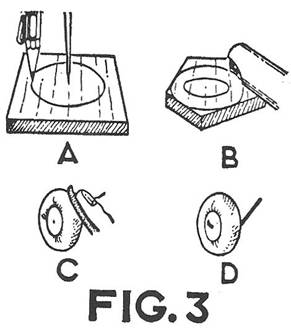
purchasing a light propeller bearing. Wheels
The two
wheels are of the solid balsa, carved type. Two pieces of balsa measuring
1/4" thick and 1" square will he needed for them. Set a compass at
1/2" and scribe a 1" diameter circle, as shown in Fig. 3,
"A." This is then cut out with the cutter, as shown at
"B." The circle is sandpapered into the form of a wheel with No.
00 sandpaper as shown at "C." Complete the second wheel in the same
manner. A center axle hole is now made through each by forcing a common pin
through the center of them. Make sure that this hole is slightly larger than
the wire landing gear, so as to permit it to turn easily when in place. Assembly All parts having been completed, the model is now ready for
assembly. Cement the elevator to the underside of the motor stick. Center the
elevator with its trailing edge at right angles to the stick and cement in
place, as shown in the plans under "Top View." Follow this by
cementing the combination rear-book and tail-skid around the end of the
stick and over the underside of the elevator, as shown in the plans under
"Side View." The rudder is cemented to the left side of the stick on top
of the elevator, when looking straight at the model from the front. See that
its leading and trailing edges are flush with those of the elevator. Cement the propeller bearing to the top center of the motor
stick at its leading end with the bent lip of the landing gear cemented
directly under it. When both are in place, silk thread is wound around them
and then coated with cement for additional strength. The wheels are slipped
over the turned up axles of the landing gear and their ends turned up to
prevent the wheels from rolling off. Attach the propeller shaft, as described last month, and
then slip its hook through the hole of the propeller hearing. Place the wing
clip around the underside of the motor stick just in front of the wing position.
Place the wing with its elevation block toward the rear on the underside of
the motor stick, as shown in the side view of the plans. The wing is held in
place with a single rubber band, Hook one loop over one of the hooks of the
wing clip. Bring the two strands of the rubber band under the wing, up and
over the stick, back under the wing and hook the other loop over the second
hook of the clip. Note the position of the center of grayitv, as shown in
the plans under "Wing" and "Side View" and designated by
the letters "C.G." Balance the model at this point under the stick
and move the wing backward and forward until perfectly balanced at this
point. Four strands of 1/8" x 1/30" flat rubber are
used for motive power. Measure the distance between the hook of the propeller
shaft and the rear hook. Multiply this distance by four, add 1/2" to this
total and cut a single strand this length. Tie the ends together and loop it
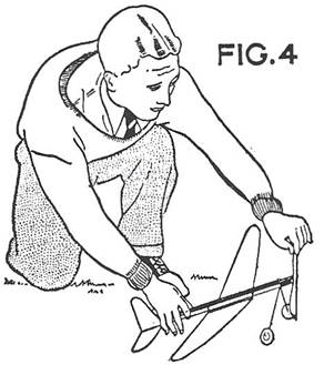
twice between the two hooks. Flying
This model will take off the ground without any assistance
from the launcher with one row of knots wound up into the rubber motor. No pushing
is necessary. Simply place it on the ground and release it. The proper way to
hold the model for launching is shown in Fig. 4. Fully wound, it will jump
immediately into the air, 275 turns may be put into the motor wound by hand.
When stretched and wound with a winder, it may be wound to 550 turns. Scanned From September, 1934 Universal Model Airplane News
|