|
Fundamentals of Model Airplane Building A New Complete Course in Model By EDWIN T. HAMILTON PART NO. 1
NOT long ago of friend of mine asked me, "How can I learn to become a model builder?" I have often been asked this question, and my reply invariably is, "By building models." That may seem a most unsatisfying answer, but its worth is to be tested by these articles, for we are going to learn model airplane building by doing just that -- building models. Each month, a different model will be used to illustrate certain principles in construction. Plans, illustrations, diagrams and step-by-step instruction will accompany each one. In this way the new modeller will not only learn to master each step, but will find himself in possession of a ready worthwhile flying model. The glider given here has been chosen for its simplicity. It incorporates many important steps in model construction and yet is not too difficult for the beginner who has never handled a piece of balsa wood in his life. Before starting any actual work, a thorough understanding of what you are going to build is essential. To gain this, read every word of these instructions. Refer constantly to both plans and illustration. Do not proceed with the next step until the first one is understood perfectly. Note that the plans accompanying this model are not given full-size. It is true that full-size plans are a great convennlence, but they teach nothing except the art of copying. All of us learned to do that in kindergarten, but none of us learned to read plans. Many model builders lack this knowledge but the time is bound to come when they will wish they had it. Those who read these articles are going to learn to read plans exactly the same as the great builders of today who make real planes, raise our great buildings and build our railroads. They do not work from full size plans, although their work is ten times as difficult as ours. We are not going to either. Let's build our models from plans exactly the same as our engineers build the real ships. In this manner we, too, will be able to step into their shoes some day and carry on. The first step in building anything is to obtain the materials from which to build it. The model given here is of a type called ''all balsa," which means exactly what it says -- that all parts are of solid balsa wood. Solid balsa wing, rudder, elevator, motor stick and elevation block. Locate each of these parts on the plan. Study their dimensions, locations and general form. Each appears in the plan under its proper name. In the advertising section of this magazine will be found a hundred different model airplane supply houses that sell balsa wood. One of the greatest aids to any model builder is to build up a "catalogue library." Write to all the companies offering catalogues. Get them and then sit down and ready study their contents. In them you will find prices, grades, sizes and other important data on balsa wood, rubber, accessories, etc. In this way you will learn which company handles certain materials which you prefer, which prices are the most reasonable and how to obtain exactly what you need. As the work progresses yon will learn to figure from the plans exactly the materials required and how much of each will be needed. For this model we must purchase the following: (A) 1 piece, 1/16" thick x 5" wide x
15-1/2" long, sheet balsa. Let us look each item over carefully, see what it's for and how we know how much of each one we need. (A) When balsa wood is purchased in thin sizes or sheets, it is called "sheet balsa," How do we know we need a sheet measuring 1/16" x 5" x 15-1/2"long? Let's turn to the plan and find out. Our main wing measures 1/16" thick, as do the elevator and rudder. Note in each of these pieces on the plan, the notation "1/16" balsa." As long as all three pieces are of the same thickness, we can order one piece of sheet balsa of that thickness and then cut each part from it. However, to do this we must measure the width and length of each part. When determining anything of this nature, always start with the longest part, which in this case is the wing. Note on the plans that our wing is 15" long on its longest side. As the combined length of the elevator and rudder is less than the length of the wing, we know that a piece of sheet balsa 15" long will prove long enough to cut all the parts from. As the ends of our wing will require cutting and sandpapering, an additional 1/2" is added to the total length for safety, which gives us the length of 15-1/2" for our piece. We now have the required thickness and length and have only to figure the width of the piece before ordering. The width of the main wing is 2-1/2" wide, while the width of the elevator and rudder is 2". As we know the rudder and elevator must be cut from the same piece as the wing, we add the width of the wing and the width of one of the other parts to gain the total necessary width of the piece. By adding 2-1/2" and 2" we know our sheet balsa piece must be 4-1/2" wide, and as they must be cut out, shaped and then sandpapered, all of which cause certain waste, we add an additional 1/2" to the width to have plenty of spare wood for these operations. With 4-1/2" of actual width and 1/2" for any waste, we know our board must be 5" wide. Some builders purchase boards considerably wider and longer than necessary so as to have extra material in case of an accident. This is good practice and is heartily recommended. In Fig. 2 will be seen the positions of each part, on this board preparatory to cutting. Note the long wing at the top, the short rudder just below it in the corner and the longer elevator next to it. In the plans at the upper right hand corner will be seen a small block which is used to give the elevator elevation. Note that its thickest portion is 1/16". It too, can be cut from this board of 1/16" balsa and it may be seen in Fig. 2 between the wing, rudder and elevator. Our next consideration is item "B." This calls for a balsa stick which is known as a "motor stick" in models having rubber motor. For gliders such as this one it actually forms the fuselage to which are attached the wing, elevator and rudder, although the rudder in this case is really cemented to the top-center of the elevator. As may be seen in the plans, this stick is 1/4" wide, 1/4" thick and 11" long, Very little work is required for finishing, and as sticks may be purchased this size, one should be ordered exactly this size. Lengths often differ and you may find it necessary to cut a longer stick to the required 11", but aside from finishing smooth with sandpaper nothing more is required. Item "C" is another type of elevation block and in this case is used for the wing. Turn to the plans under "Front View" and you will locate this part under "Block." Its side view is shown under "Side View" in the plans. As it fits and covers the top of the motor stick, it must be 1/4" thick. As it extends the full width of the wing, it must be 2-1/2" long and as it raises the wing 1" above the stick its width must be 1". Be sure to cut it so the grain of the wood runs across the block. These items complete the list of necessary balsa wood. Item "D" is any ordinary rubber band large enough to stretch at least 2-1/2" long. It is used to hold the elevator in position on the stick. It is shown in the plans under "Side View" and "Plan" by its proper name "Rubber Band." In Fig. 6 is shown how it is applied, The soft wire (E) is used to wrap around the front end of the stick to make the model balance at its proper center of gravity, which appears in the plans under "C.G." A small can of model airplane clear cement (F) should be purchased, as well as one or more sheets of No. 00 (very fine) sandpaper (G). Tiny model pins (H) are very useful for a hundred different reasons in model building. For this model we use them to hold the block in place on the stick until the cement has hardened, which takes only a second or two. These complete our necessary materials. Gather them together on any empty table and let's get to work!
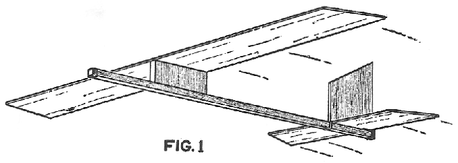
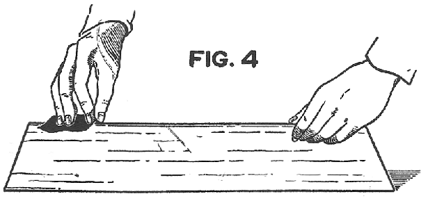
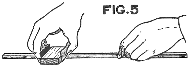
Our first job is to lay out the wing, rudder, elevator and small elevation block on our sheet balsa piece. Study each part. Note that they have their ends cut at a slight angle. Lay out each of these pieces as shown in Fig. 2. When measuring them, make each a perfect rectangle. Then measure along one long edge of both the wing and elevator and mark points 1/2" in from each end. Join these points with the ends of the other edge, which completes their form. The rudder has a 1" angle on only one end. Measure this and join it with the other end. Test to see that the sides of all pieces are parallel with each other and the proper distance apart. We are now ready to cut out these parts from the balsa sheet. A razor blade is best for this work, although if you have a sharp knife and cannot locate a razor blade, it may be used. A small cutter can be easily made, as shown in Fig. 3. It consists of a 6" length of dowel stick or a broom handle, cut at a slant at one end and then slotted to take a safety razor blade. Cement the blade in place. Whenever cutting balsa wood, use a steel edge school rule to guide your lines, cut very slowly and take care that your cuts are slightly outside the lines. When each piece has been cut out, they should be finished with sandpaper. Whenever using sandpaper, always stroke with the grain of the wood. For rounded edges, such as is required for the wing of our glider, use the sandpaper in the bare hand, as shown in Fig. 4. Note that one hand holds the wing on edge, while the other hand sands the other edge. Lightly sandpaper both faces of all parts, round both edges of the main wing, as shown in the plans under "Side View" and leave the other parts with squared edges. When using sandpaper on fiat surfaces which you wish left flat, always use a small block of wood, as shown in Fig. 5. Study the form of the small elevation block shown under "Side View" in the plans. Note that it is given the form of a wedge, being the full 1/16" at one end and tapering off to 1/32" at the other. Complete this piece by sandpapering it to proper shape. This completes the wing, rudder, elevator and elevation block. The wing elevation block requires no work except cutting to exact size, which is 1/4" x l" x 2-1/2" and then sandpapering smooth, Do this lightly so as not to cut down its size. Cut the 1/4" x 1/4" stick of balsa exactly 11" long and smooth with sandpaper used with a block of wood so as to prevent rounded edges. Note this in Pig. 5. All parts are now finished and we are ready to assemble our glider. Assembly When all parts of a model have been correctly and carefully finished, many model builders ruin their good work by hurrying and making a poor assembly. Show me a poorly assembled model and I'll show you a poor flier. If you were ever patient in any work, be so now for it is vitally important to the success of your entire work. Study the illustration in Fig. 1 showing the completed and assembled model. Note where each part is located. Choose one end of the fuselage stick and mark it for the front. From this end, measure 3-11/16" and mark. This point is the center of gravity when the glider has been properly balanced with the wire. Measure 7-1/2" from either end of the wing and mark. This should be its exact center. Draw a line from side to side. Measure from one end of the elevation wing block a distance of 1" and mark. This mark and the center of gravity mark on the stick must be directly in line with each other when the block is in proper place on the stick, as shown in the "Side View" of the plans under "C.G." Coat the bottom edge of this block with cement, place it in position on the stick so that the mark on the block and the mark on the stick come together, and hold in position with two model pins thrust through the stick and up into the edge of the block. Allow the pins to protrude so that they can he easily removed. The wing is then cemented on top of the block so that its edges match the edges of the block and the center line of the wing comes exactly in the center of the block's upper edge. Test to see that the wing is level with the stick and at right angles to it. Model pins may hold it in place until the cement has hardened. Allow fifteen minutes before removing the pins. The "tail unit" which consists of the elevator and rudder, is now assembled. Find the exact center of the elevator by measuring 3" from either of its ends along its longest edge. Mark and then draw a line from side to side. Coat the rudder with cement along its squared end and place along the center line of the elevator so that the rudder is directly centered on it. See that the rudder and elevator form right angles. Hold by pushing model pins through the elevator and up into the edge of the rudder. When thoroughly hardened, the pins are removed and the unit assembled on the stick. This is done with the rubber band and is shown in Fig. 6 in three steps. Pass the rubber band over the end of the stick and work it along until in front of the elevator when in place. Place the elevator in place on the stick so that its trailing edge is about 1/4" in from the end of the stick. This is shown in Fig. 6 "A." The loop of the band is now stretched over the elevator and rudder and brought under the end of the stick, as in "B." In "C" is shown the elevator in place held by the rubber band. In these illustrations, the rudder is purposely left off the elevator to make the picture more dear.
Balancing The glider must now be properly balanced. This is done by wrapping soft wire around the end of the stick as shown in the plans. Just enough of the wire should be wrapped around the stick to make the entire model balance evenly on its point of center of gravity. Start wrapping wire around the end of the stick. Balance the model at the exact point marked on the stick as the center of gravity. When the balancing is perfectly even, stop wrapping. The small elevation block for the elevator is used to obtain angle for this surface, which in turn will regulate the climb of the glider. By pushing the block well under the elevator, the glider will tend to climb. By pulling the block back so that less height is given to the rear portion of the elevator, the climb is lessened. If the glider should still climb too steeply and then tend to stall, this may be corrected by adding a little more weight to its nose, which is done by adding wire around the end of the stick. The elevator block, when once properly set, should be cemented in place on the stick, but do not cement the elevator to it. This is held with the rubber bands. Launch your model from a hill or high elevation. Scanned From May, 1934 |


